


![New iPad 11 (A16) On Sale for Just $277.78! [Lowest Price Ever]](https://www.iclarified.com/images/news/97273/97273/97273-640.jpg)

![Apple Foldable iPhone to Feature New Display Tech, 19% Thinner Panel [Rumor]](https://www.iclarified.com/images/news/97271/97271/97271-640.jpg)
![Apple Shares New Mother's Day Ad: 'A Gift for Mom' [Video]](https://www.iclarified.com/images/news/97267/97267/97267-640.jpg)


-xl.jpg)


 Evolved as a Predominant Framework for Ransomware Attacks.webp?#)


![[The AI Show Episode 146]: Rise of “AI-First” Companies, AI Job Disruption, GPT-4o Update Gets Rolled Back, How Big Consulting Firms Use AI, and Meta AI App](https://www.marketingaiinstitute.com/hubfs/ep%20146%20cover.png)


![Ditching a Microsoft Job to Enter Startup Hell with Lonewolf Engineer Sam Crombie [Podcast #171]](https://cdn.hashnode.com/res/hashnode/image/upload/v1746753508177/0cd57f66-fdb0-4972-b285-1443a7db39fc.png?#)


-Nintendo-Switch-2-Hands-On-Preview-Mario-Kart-World-Impressions-&-More!-00-10-30.png?width=1920&height=1920&fit=bounds&quality=70&format=jpg&auto=webp#)


.jpg?width=1920&height=1920&fit=bounds&quality=70&format=jpg&auto=webp#)


Oscilloscope Digital Storage, 1990s Style
You’re designing an oscilloscope with modest storage — only 15,000 samples per channel. However, the sample rate is at 5 Gs/s, and you have to store all four channels at …read more
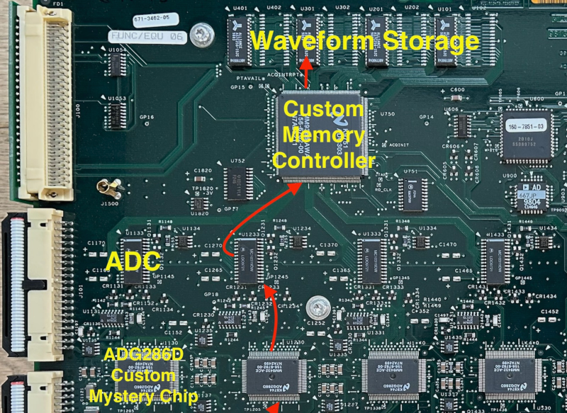

You’re designing an oscilloscope with modest storage — only 15,000 samples per channel. However, the sample rate is at 5 Gs/s, and you have to store all four channels at that speed and depth. While there is a bit of a challenge implied, this is quite doable using today’s technology. But what about in the 1990s when the Tektronix TDS 684B appeared on the market? [Tom Verbure] wondered how it was able to do such a thing. He found out, and since he wrote it up, now you can find out, too.
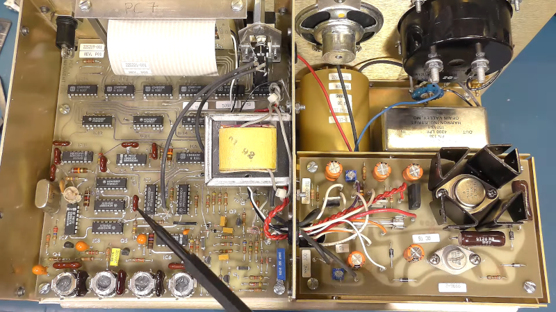
Inside the scope, there are two PCBs. There’s a CPU board, of course. But there’s not enough memory there to account for the scope’s capability. That much high-speed memory would have been tough in those days, anyway. The memory is actually on the analog board along with the inputs and digitizers. That should be a clue.

The secret is the ADG286D from National Semiconductor. While we can’t find any info on the chip, it appears to be an analog shift register, something all the rage at the time. These chips often appeared in audio special effect units because they could delay an analog signal easily.
In practice, the device worked by charging a capacitor to an input signal and then, using a clock, dumping each capacitor into the next one until the last capacitor produced the delayed output. Like any delay line, you could feed the output to the input and have a working memory device.
The scope would push samples into the memory at high speed. Then the CPU could shift them back out on a much slower clock. A clever design and [Tom] gives us a great glimpse inside a state-of-the-art 1990s-era scope.
While we haven’t seen the ADG286D before, we have looked at analog shift registers, if you want to learn more.