


![Apple's F1 Camera Rig Revealed [Video]](https://www.iclarified.com/images/news/97651/97651/97651-640.jpg)

![Apple Shares New Apple Arcade Ad: 'Hold That Train!' [Video]](https://www.iclarified.com/images/news/97653/97653/97653-640.jpg)
![Apple Shares New Shot on iPhone Film: 'Big Man' [Video]](https://www.iclarified.com/images/news/97654/97654/97654-640.jpg)


_Brain_light_Alamy.jpg?width=1280&auto=webp&quality=80&disable=upscale#)


![[The AI Show Episode 153]: OpenAI Releases o3-Pro, Disney Sues Midjourney, Altman: “Gentle Singularity” Is Here, AI and Jobs & News Sites Getting Crushed by AI Search](https://www.marketingaiinstitute.com/hubfs/ep%20153%20cover.png)


.png?width=1920&height=1920&fit=bounds&quality=70&format=jpg&auto=webp#)


The Data Communication and Networking Handbook
When I was beginning to learn about networks, I didn't know how many things in my daily life depended on them – from texting on WhatsApp to watching YouTube. I still vividly remember when I learned that computers communicate with one another. It was ...

When I was beginning to learn about networks, I didn't know how many things in my daily life depended on them – from texting on WhatsApp to watching YouTube.
I still vividly remember when I learned that computers communicate with one another. It was magic – telepathy, nearly. But there is a systematic, logical process behind the magic: computer networking. And I’m excited to help you discover how computers communicate and why it’s possible.
Essentially, data communication is all about exchanging information between two or more machines. But it's not just a question of sending – it's a matter of sending the right data, to the right machine, in the right format. And that's the brilliance of networking basics.
This handbook will teach you the fundamentals of the language of computers. You'll discover how data is passed from machine to machine, how operations are carried out on information, and how networks – from tiny home arrangements to massive worldwide networks – are constructed and managed.
We’ll start with the absolute basics: what a network is, what the hardware is, and how devices know each other and talk to each other. Next, we’ll examine crucial networking models like OSI and TCP/IP stacks that segment communication into layers in order to make it easier to understand and troubleshoot. You'll learn about IP addresses, DNS, routing, switching, and firewalls and security's involvement in keeping networks safe.
Whether you are a complete beginner starting from the ground up or a seasoned dev looking to solidify your foundation, this handbook will walk you through linking the dots. When you're finished, you won't only understand how your favorite sites and apps really function behind the scenes – you'll be able to speak networks in your sleep.
Table of Contents
Chapter 3: Bandwidth — Understanding How Much We Can Transmit
Chapter 4: Transmission Media — The Highways of Communication
Chapter 5: Network Topologies — How We Structure Our Connections
Chapter 6: The OSI Model — Understanding Layers of Communication
Chapter 7: Protocols and Ports — How Rules and Doors Guide Communication
Chapter 8: IP Addressing and Subnetting — Naming and Organizing the Network
Chapter 9: Routing and Switching — Directing Data on the Network
Chapter 10: Network Infrastructure — Devices, Security, and the Modern Internet
Chapter 1: Data and Communication Fundamentals
This introductory section lays the groundwork for the rest of the handbook. You’ll learn what data communication is, how it's different from "sending a message," and what's required for two computers (or phones, or servers) to exchange information efficiently.
You'll start to feel at home with fundamental ideas, technical terminology, and the machinery behind the scenes that works quietly in the background to make daily technology appear effortless.
By the end, you will be able to:
Explain what data communication is and how it works in real life
Identify the components involved in data communication systems
Differentiate between types of data and how they're represented
Understand different types of data flow (simplex, half duplex, full duplex)
Describe what a computer network is and its main categories (LAN, MAN, WAN)
Understand the importance of protocols and how they enable communication
Recognize the role of standards and standard organizations in making networking universal
Data vs Information
We throw around the word "data" a lot these days – "big data," "data science," "data plans" – but what does it mean?
Data is raw. It's unprocessed, meaningless on its own. Think of numbers on a spreadsheet with no labels.
Information is processed data – it's meaningful and helps us make decisions.
A personal example: I once received a CSV file from my school with hundreds of rows of marks. It looked like chaos – just student IDs and scores. But the moment I matched those IDs to names and applied the grading criteria, it became useful information about who passed, who failed, and who topped the class.
So, data is the ingredient. Information is the cooked dish.
So, What Exactly is Data Communication?
Imagine you're texting your friend. Your phone sends data to their phone using signals through cables, Wi-Fi, or even satellites. This entire process is called data communication, moving data from one place (you!) to another (your friend).
But it’s not as random as it sounds. It follows a set of agreed rules called protocols. Think of them as social etiquette for devices – how to talk, when to talk, and what to say.

This process involves:
Devices (sender and receiver)
A transmission medium (like cables or wireless)
A set of rules (protocols)
Let’s break it down further.
Characteristics of Data Communication
To be considered effective, data communication must exhibit the following characteristics:
Delivery: Data must reach the correct destination. If I send a message to John, it shouldn't land in Sarah's inbox.
Accuracy: No one wants a corrupted file. Data must be accurate, free from errors.
Timeliness: Some data, like live video, must arrive on time. Lag ruins the experience.
Jitter: Inconsistent arrival times of data packets (especially in audio/video) create disruption. A good system keeps jitter low.
I once experienced a video call where the sound lagged by 5 seconds. It turned into a game of "Guess what I said." That's jitter in action.
Meet the Cast: The Components of Data Communication
In every data conversation, five key players show up:
Sender – The device that starts the chat (like your phone).
Receiver – The one getting the message (your friend’s phone).
Message – The actual info, whether it’s "hi" or a TikTok.
Transmission Medium – The path your message travels (Wi-Fi, cables, and so on).
Protocol – The language they agree to speak (like TCP/IP).
Pretty cool, right?

Data Representation
Computers are not humans. They don’t understand language, pictures, or music – unless these are converted into a format they can process: bits (0s and 1s).
Let’s walk through the different types of data representation:
1. Text
Text is stored as a sequence of characters using encoding schemes like ASCII and Unicode. For example, the letter "A" in ASCII is 65, which in binary is 01000001.
2. Numbers
Similarly, numeric data is stored as bit patterns. Computers can perform calculations using binary logic.
3. Images
An image is a matrix of pixels. Each pixel is represented by bits. A black-and-white image might only need 1 bit per pixel, while a full-color photo could use 24 bits per pixel or more.
Example: A 10x10 black and white image = 100 pixels = 100 bits.
4. Audio
Audio is analog, but we digitize it for storage and transmission. For instance, voice notes are sampled at certain intervals and stored as bits.
5. Video
Video is a sequence of images (frames) along with synchronized audio. It’s high in data volume and needs compression techniques like MP4 to be practical.
How Does the Data Flow?
You might think data just zips across in one go – but it has modes, just like moods:
Simplex: One-way only (like a radio broadcast).
Half Duplex: You take turns – like walkie-talkies.
Full Duplex: Both sides talk at once – think phone calls.
Each has its own vibe depending on the situation.

What is a Computer Network?
A computer network is a system that allows devices to share data. These connected devices (nodes) use communication links to interact.
The main goals of a network are:
Reliability: Data should get there.
Security: Unwanted access should be blocked.
Performance: High speed, low delay.
When you connect your laptop at a café, for example, you’re part of a network. But networks come in all shapes:
- PAN (A personal area network): connects electronic devices within a user's immediate area.

- LAN (Local Area Network): Small – like your home Wi-Fi.

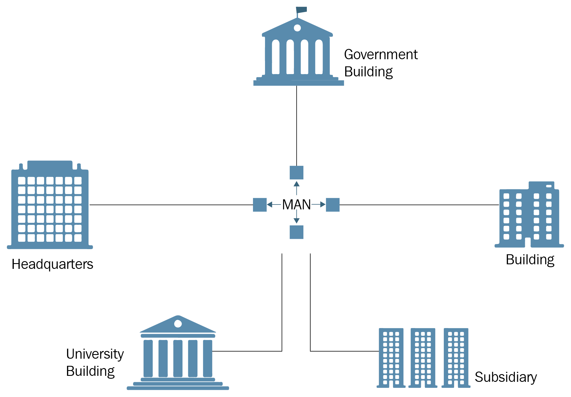
- MAN (Metropolitan Area Network): Covers a city – like college campuses.
- WAN (Wide Area Network): Huge – think the entire internet!

The internet isn’t one big net – it’s a net of many, many nets.
What is a Protocol?
A protocol is a set of rules that devices follow to communicate. Without a protocol, it’s chaos.
Analogy: Think of a group project. If everyone agrees to use Google Docs and write in English (or any one language), it works. But if one person uses Word in French, and another emails a PDF in Mandarin, you have a mess.
Protocols define:
What data to send
How to send it
When to send it
Elements of a Protocol
Syntax: Format and structure (like grammar).
Semantics: Meaning of each section.
Timing: When to send and at what speed.
Standards in Networking
Standards are agreements to ensure that different systems can work together. Without standards, each manufacturer would create isolated networks that couldn’t talk to others.
There are two types of standards:
De facto: By convention (used commonly but not formally approved)
De jure: By law (formally approved)
Standards Organizations
There are a few key organizations that help define these standards:
ISO – International Organization for Standardization
ITU-T – International Telecommunication Union
IEEE – Institute of Electrical and Electronics Engineers
ANSI – American National Standards Institute
EIA – Electronic Industries Association
Chapter 2: Signals — The Language of Communication
In this chapter, I’ll teach you about the invisible messengers – signals – that make it all possible. You will:
Understand what signals are and how they carry data
Distinguish between analog and digital signals, and when each is used
Learn about key signal characteristics like amplitude, frequency, phase, and wavelength
Visualize and compare time domain vs frequency domain representations
Appreciate how real-world signals are composed of multiple waves (composite signals)
Understand digital signal features like bit rate, baud rate, and bit interval
Learn about baseband vs broadband transmission methods
Identify challenges like attenuation, distortion, and noise
Grasp how bandwidth affects data quality and speed
When I was a teenager, I often wondered how my voice traveled through a phone and reached someone else in another town. I imagined tiny versions of myself running through wires with a message in hand. Turns out, while not exactly accurate, the idea of something carrying your message is spot on. That something is called a signal.
A signal is the form data takes to move through physical space. Whether it’s your mom calling you, your professor sending an email, or your friend uploading a reel – all of that happens through signals.
Data and Signals
What is a Signal?
I learned that data is like the message I wanted to send, and a signal is the delivery truck. Without the truck, the message goes nowhere.
Here’s where things get a bit science-y, but stay with me. When data travels, it becomes signals, kind of like waves. These waves can be classified in to two common ways, by the nature of the signal, and by their patterns over time. We’ll talk about the nature of the signal first.
The Nature of the Signal: Analog vs Digital
Analog – A signal that varies smoothly over time and can take any value in a range. Like ocean waves, always changing smoothly. Continuous (like voices).
Digital – A signal that has discrete values, usually 0s and 1s. Like a staircase – clear, sharp steps, either up or down, in bits (1s and 0s, like computers).

Analog Signals
The first time I visualized an analog signal, it looked like the ripples I saw after tossing a stone in water. Gentle curves moving outwards.
Key features of analog signals:
Amplitude: This reminded me of volume. Louder signals have taller waves.
Frequency: It’s the beat or rhythm. High frequency = rapid waves = higher pitch.
Period: Time for one full wave cycle. Shorter periods mean higher frequency.
Phase: Two waves can start at different points – just like dancers starting a move a second apart.
Wavelength: How far one wave travels in space. It depends on how fast it moves and its frequency.
Time vs. Frequency Domain
Time Domain: Shows how signals change over time. Like watching a song’s audio waveform.
Frequency Domain: Shows the ingredients – how much bass, how much treble. It’s like the EQ settings on a music player.
Composite Signals and Fourier
Real-world signals are messy, made of multiple waves mixed. Fourier’s big idea was: Any messy signal can be broken down into simple sine waves. That insight changed how engineers understand and clean up signals.
Digital Signals
Digital signals felt familiar to me. My laptop, my phone, even my microwave speaks digital.
Key features of digital signals:
Bit Interval: One bit’s duration. Like how long I hold down a piano key.
Bit Rate: How many notes (bits) I can play per second.
Baud Rate: How often the signal actually changes. Not always the same as bit rate.
Levels: 2-level = 1s and 0s. More levels = more complex encoding.
Square Waves
If analog signals are elegant curves, digital signals are sharp edges. A square wave is a bold, binary shout: ON-OFF-ON-OFF.
Digital Advantages and Struggles
Why I love them:
They’re clean and easy to work with.
Errors are easier to spot and fix.
But they’re not perfect:
They need more bandwidth.
They don’t travel well over long distances without help.
Pattern Over Time: Periodic vs Non-periodic Signals
Periodic Signals: Repeat at regular intervals over time (for example, sine waves, clock pulses).
Non-periodic Signals: Do not repeat – more random or unique (for example, a burst of data or speech waveform).

Periodic Signals
These feel like the rhythm of my favorite song. They’re predictable. Repeating. Reliable.
Key Features
Repetition: The same pattern, again and again. Like waves hitting the shore at steady intervals.
Cycle: One complete shape of the signal. Think of it as one heartbeat in a steady pulse.
Frequency: How many cycles per second? Measured in Hertz (Hz).
Why I like them
Easy to analyze – like having a beat to follow.
Great for systems that need synchronization, like clock signals in my devices.
But still...
- They can’t carry surprise or variety. No space for one-time messages.
Non-periodic Signals
These are the jazz solos of the signal world. Wild. Unique. Unpredictable.
Key Features
No repetition: Each part is different – like my playlist on shuffle.
Spikes and silence: Sudden changes, long pauses. Perfect for one-off data transmissions.
Used in real-life data: Emails, videos, and downloads all love this format.
Why they’re cool
Great for representing actual information – each burst means something new.
More flexible for transmitting complex messages.
What’s tricky
Harder to analyze and predict.
Tougher to filter or compress efficiently.
Understanding signals helps us know how fast and cleanly information travels.
Channels: The Roads Signals Travel On
In the context of signals and communication, channels refer to the medium or path through which a signal travels from a sender (transmitter) to a receiver. Channels are like roads. You can’t just send a truck (signal) without knowing if the road (channel) allows it.
We can describe channels in different ways:
Physically: What the signal travels through (like a wire or air).
Functionally: How the signal is allowed to move through (based on frequency).
Logically: How we organize multiple data streams within the same physical path.
Physical Channels = The Road Itself
These are the real, tangible paths for signals:
| Example | Medium |
| Ethernet cable | Copper wire |
| Fiber-optic link | Glass strand |
| Wi-Fi or Radio | Air (wireless) |
| Satellite transmission | Space (electromagnetic waves) |
Frequency Behavior of Physical Channels
Just like roads are built for certain speeds, physical channels are better at carrying certain frequencies.
Here’s where low-pass, high-pass, band-pass, and band-stop come in – they describe how a physical channel behaves.
| Channel Type | Behavior | Analogy | Common Use |
| Low-pass | Lets low frequencies pass | Quiet country road (slow cars only) | Telephone lines (voice) |
| Band-pass | Allows a specific frequency band | Toll road with speed range | FM radio, Wi-Fi |
| High-pass | Blocks low, passes high frequencies | Speedway (fast cars only) | Audio filtering |
| Band-stop | Blocks a range but passes others | Road under construction | Noise removal (for example, hum filter) |
So when we say "low-pass channel," we're talking about how a physical channel filters signals.
Logical Channels = Lanes on the Road
A logical channel is a virtual path created within a physical one. It organizes or splits the signal flow so multiple people or devices can use the same channel without crashing into each other.
| Feature | Description | Analogy |
| Frequency Division | Each user gets their own frequency | FM radio stations |
| Time Division | Each user gets a time slot | Taking turns at a speaking table |
| Virtual Circuits | Custom paths inside networks | Reserved bus seats |
So yes – you can have many logical channels on one physical cable.
How They Work Together
Let’s combine it all:
Imagine a fiber optic cable (physical channel) that’s designed to carry a specific frequency range (band-pass).
Within that frequency range, you can create many logical channels using time or frequency division.
Example: FM Radio
Physical Channel: Air (radio waves)
Type: Band-pass (88–108 MHz)
Logical Channels: Each station (for example, 98.4 FM) is a logical channel inside that band
Example: Internet over DSL
Physical Channel: Telephone line (copper wire)
Type: Low-pass for voice, high-pass for internet
Logical Channels: Browsing, streaming, and downloads running together via time/frequency division
Baseband vs Broadband Transmission: How We Use the Channel
There are two main types of ways we use the channel: baseband and broadband transmission.
Baseband Transmission is like talking directly to someone across a quiet room. Simple and unaltered. Common in local systems like Ethernet.
Broadband Transmission is a bit different. Here, we dress up the digital message in analog clothing using modulation. That’s how we send data over radio or fiber. It’s more complex, but necessary when you’re dealing with wider, noisier roads.
Signal Villains: What Goes Wrong on the Way
As your signal travels down the channel, it may face three big problems.
Attenuation: It’s like my voice getting quieter the farther I am from someone. Amplifiers help boost it.
Distortion: Imagine you and I agree to send square waves, but by the time it reaches you, it looks like mush. That’s distortion, especially bad over long cables.
Noise: Noise is anything extra that wasn’t supposed to be in the signal. From lightning strikes to microwaves, interference is real.
Types I learned about:
Thermal (heat-related)
Induced (nearby equipment)
Crosstalk (adjacent wires “talking”)
Impulse (sudden bursts)
We can reduce noise using better cables, filters, and digital corrections.
Bandwidth
The word ‘bandwidth’ gets thrown around so much. For me, it used to just mean internet speed. But it’s deeper:
Analog Bandwidth: Range of frequencies a signal uses.
Digital Bandwidth: How much data we can push through per second.
More bandwidth = more room = faster, clearer communication.
We’ll talk more about bandwidth in the next chapter.
Learning about signals was like being handed the key to a secret code. Every beep, flash, and wave in our world is part of a language. Once you see it, you can’t unsee it. Signals are not just theory – they are the reason I can write this on a laptop, send it to the cloud, and have you read it anywhere in the world.
Chapter 3: Bandwidth — Understanding How Much We Can Transmit
When I first heard the term "bandwidth," I assumed it just meant how fast my internet was. And while that’s not entirely wrong, I came to learn there’s much more to it.
In this chapter, we’ll delve into the concept of bandwidth as the capacity of a communication path, examine its impact on signal quality and speed, and investigate how it's measured in both analog and digital systems.
By the end of this chapter, you will be able to explain:
What bandwidth means in different contexts
How analog and digital bandwidths are measured
The concept of throughput and how it differs from bandwidth
Factors that affect data transmission performance
What Bandwidth is All About
Bandwidth is the maximum amount of data that can be transmitted over a communication channel in a given amount of time.
Have you ever streamed a movie and it kept buffering? That frustrating lag led me to one of the most important concepts in networking: bandwidth. Bandwidth is like a highway. The wider the road, the more cars (or data) can pass at once.
I also like to think of it this way: If I’m trying to pour water (data) through a pipe (the communication channel), a narrow pipe limits how much water can flow through at a time. That’s low bandwidth. A wide pipe? Now we’re talking high bandwidth – fast and smooth.
Bandwidth Utilization
Efficiency
This is how well we use the available bandwidth. High efficiency means most of the bandwidth is being used for actual data (not overhead).
Overhead
Overhead includes headers, acknowledgments, and error-checking codes. It’s necessary, but it eats into our available bandwidth.
Idle Time
Sometimes the channel sits unused, due to waiting for acknowledgment, processing time, and so on. Minimizing idle time improves efficiency.
Bandwidth in Analog and Digital Terms
Analog Bandwidth
Analog bandwidth refers to the range of frequencies over which an analog signal can be accurately acquired, processed, or transmitted by a system. Beyond this range, the signal begins to degrade – either being attenuated or distorted, making it unreliable for precise use.

Key Concepts
Frequency Range: Analog bandwidth defines the spectrum of frequencies that a system can handle without significant degradation. It’s the system’s “comfort zone” for signal fidelity.
3 dB Bandwidth: One common method of defining analog bandwidth is the -3 dB point. At this point, the signal’s amplitude drops to about 70.7% of its original value, meaning almost half its power is lost. Frequencies beyond this threshold experience much more signal loss or distortion.
Importance in Signal Fidelity: Analog bandwidth directly affects how well a system can reproduce or process real-world signals – especially in audio, video, instrumentation, and telecommunications. A narrow bandwidth results in muffled or distorted outputs, while a wider bandwidth ensures better detail and accuracy.
Bandwidth and Rise Time
In instruments like oscilloscopes, analog bandwidth is closely related to rise time – the time it takes for a signal to transition from low to high. A wider bandwidth enables faster transitions to be captured accurately, which is essential for analyzing high-speed or fast-changing signals.
Real-Life Example
Consider old telephone systems: they typically had an analog bandwidth ranging from 300 Hz to 3300 Hz, resulting in a 3000 Hz bandwidth. This range was enough for clear voice transmission, but not wide enough for high-fidelity music or modern audio standards.
Applications of Analog Bandwidth
| Application Area | Role of Analog Bandwidth |
| Oscilloscopes | Determines how accurately signals (especially fast ones) are captured. |
| Amplifiers | Specifies which frequency ranges can be amplified without distortion. |
| Communication Systems | Defines signal capacity and transmission quality. |
| Data Acquisition | Affects how well fast-changing signals are measured and analyzed. |
Digital Bandwidth
Digital bandwidth refers to the maximum capacity of a digital channel to transmit data over a specific period, usually measured in bits per second (bps). It’s a measure of how much data can “flow” through a communication path, much like how the width of a pipe controls how much water can pass through.
The wider the digital bandwidth, the more data can be transmitted simultaneously, resulting in faster downloads, smoother video streams, and better overall network performance.
Bandwidth vs. Data Rate
Although they’re often used interchangeably, they aren’t quite the same:
Bandwidth is the capacity of the channel – the maximum potential.
Data rate is the actual speed at which data is transmitted, which can vary based on factors like:
Network congestion
Hardware limitations
Signal interference
Think of bandwidth as the size of a highway, and data rate as how fast cars are moving on it.
How Digital Bandwidth is Measured
Digital bandwidth is expressed in units such as:
bps – bits per second
Kbps – thousands of bits per second
Mbps – millions of bits per second
Gbps – billions of bits per second
Example: A 100 Mbps internet connection can, in theory, transfer 100 million bits of data every second.
Why It Matters
Bandwidth plays a central role in modern digital life. Without enough bandwidth:
Streaming videos buffer
Video calls drop in quality or disconnect
Online games lag or stutter
Large files download painfully slowly
This becomes even more critical when multiple devices share the same network. Each device draws from the available bandwidth, which can quickly get overwhelmed if the demand is too high.
Digital vs. Analog Bandwidth
| Aspect | Digital Bandwidth | Analog Bandwidth |
| Measured in | Bits per second (bps, Mbps, Gbps) | Hertz (Hz) |
| Focus | Data transmission rate | Frequency range |
| Example | Internet connection | FM radio signal (for example, 88–108 MHz) |
Bandwidth in Shared Networks
In shared environments – like home Wi-Fi or public hotspots – everyone taps into the same bandwidth. If bandwidth is limited and several devices are streaming, gaming, or downloading, the network slows down for everyone.
Throughput – What Gets Delivered
While bandwidth is the potential capacity of a channel (the width of the road), throughput is the actual rate at which data travels end‑to‑end under real‑world conditions. It’s the number of cars that make it through the city per minute, after red lights, speed limits, and detours.
Key factors that influence throughput:
Interference & Noise (analog) or packet collisions (digital)
Hardware Constraints (CPU, NICs, switches)
Network Congestion (too many users/devices)
Error Retransmissions (when packets get lost or corrupted)
Example: A “100 Mbps” link (bandwidth) might only sustain 80 Mbps of throughput because of TCP overhead, competing traffic, and occasional packet losses.
Latency and Delay – The Time Dimension
Latency is the time it takes for a single bit (or packet) to travel from sender to receiver. Think of it as a travel time, whereas bandwidth and throughput are about volume.
Propagation Delay: Time for the signal to move through the medium (for example, light in fiber: ~200,000 km/s).
Transmission Delay: Time to push all the bits of a packet onto the wire:
Packet Size (bits)÷Link Bandwidth (bps)\text{Packet Size (bits)} ÷ \text{Link Bandwidth (bps)}Packet Size (bits)÷Link Bandwidth (bps)Processing Delay: Time routers or switches spend examining headers, making forwarding decisions.
Queuing Delay: Time packets wait in buffers when traffic spikes.
Real‑world story: During a long‑distance video call, even 100 ms of round‑trip latency can feel like talking through molasses – voices overlap, and the conversation feels stilted.
Jitter – Variability in Arrival
Jitter is the inconsistency in packet arrival times. Even if the average latency is low, high jitter disrupts:
Audio/Video Streams: Choppy playback when packets clump or arrive too late.
VoIP Calls: Glitches, echoes, or dropped words.
You can mitigate this through Buffers and Quality of Service (QoS) agreements, which real‑time traffic to smooth out the delivery.
How to Improve Performance
If I could go back in time and give myself one tip: Performance isn’t just about speed – it’s about reliability and consistency, too.
Here’s what affects performance:
Bandwidth: Think of this as the largest diameter of your internet pipe – how much data can actually move through it per second, usually in Mbps or Gbps.
Why it matters: More bandwidth means your connection can handle more data – like downloading big files fast or streaming in 4K. BUT: Just because your connection can go fast doesn't necessarily mean that it always does. That's where throughput comes in.
Throughput: Your actual speed – how much data is really passing through the pipe right now.
Why it matters: Your actual internet experience (web page loading, Netflix streaming, gaming) is throughput-dependent, not bandwidth-dependent. If your throughput is bad, your videos buffer, downloads crawl, and games lag – even when you're signed up for a "fast" plan.
Latency & Jitter: Latency is the lag – how long it takes information to travel from your machine back to the server and vice versa (in milliseconds). Jitter is the variation in that lag – how inconsistent the timing gets.
Why they're significant: High latency = frustrating delay in video calls, sluggish online gaming, or keyboard lag in remote desktops. High jitter = choppy audio, frozen faces, or desync'd video in live meetings or streams.
Packet Loss: Sometimes, data just doesn't get to where it’s supposed to go. Packets are tiny chunks of data, and if a few get lost along the way, your device has to ask for them again.
Why it matters: Small levels of packet loss can cause buffering, call drops, or rubberbanding during gaming. Greater loss = subpar performance, stuttery audio, or crashed streams.
Utilization & Overhead: Utilization refers to what ratio of your total bandwidth is being used at any one time. Overhead is the extra information that needs to be dealt with to manage your connection – like labels on a package.
Why they're important: High utilization is when your connection gets crowded – for example, rush hour. Everything slows down. High overhead absorbs your free bandwidth – less room for what you actually love (video, games, files).
Engineers use techniques like compression, efficient routing, better cabling, and load balancing to improve performance.
I now see bandwidth everywhere – not just in networks, but in life. Our mental bandwidth, emotional bandwidth – it's all about capacity. Knowing how bandwidth works helped me troubleshoot slow Wi-Fi, plan file transfers, and appreciate what’s going on behind a simple Google search.
Just as in life with mental or emotional bandwidth, we need both capacity and consistency to function at our best. Understanding these metrics empowers you to diagnose slow Wi‑Fi, optimize file transfers, and build networks that meet real user demands.
Chapter 4: Transmission Media — The Highways of Communication
How does data move across distances? What path does it take?
This chapter dives into the physical and wireless pathways data takes from one device to another – the transmission media. By the end of this chapter, you will understand:
What transmission media is and why it matters
The difference between guided (wired) and unguided (wireless) media
Various types of cables (twisted pair, coaxial, fiber optics)
Wireless media like radio waves, microwaves, and infrared
The strengths and limitations of each medium
What are Transmission Media?
Imagine needing to deliver a letter. Do you send it through a postal truck? Drop it by drone? Deliver it by hand? The method you choose is your transmission medium.
In the digital world, transmission media refers to the path data takes from the sender to the receiver. These paths can be physical (guided), like cables, or wireless (unguided), like airwaves.
When I finally understood that even invisible data needs a “road,” I realized how crucial this topic was to building fast, reliable networks.
Different Types of Transmission Media
Transmission media are classified into two broad categories:
Guided Media (Wired): The data follows a specific path (like a road or railway). Common types include a Twisted Pair cable, a Coaxial cable, and a Fiber Optic cable.
Unguided Media (Wireless): Data floats freely through the atmosphere, like radio signals or Wi-Fi. Types include Radio Waves, Microwaves, and Infrared Waves.
Let’s dive into each of these types of transmission media in a bit more detail.
Guided Transmission Media

1. Twisted Pair Cable
This was the first cable I ever handled – it looked like two wires twisted together. Signals are transmitted as tiny voltage differences between the two copper conductors. By twisting the pair, electromagnetic interference picked up on one wire tends to be canceled out on the other, since each twist reverses their positions relative to the noise source.
Features & Use‑Cases:
Structure: Two insulated copper wires twisted to reduce interference.
Types:
Unshielded Twisted Pair (UTP): Common in LANs, cheaper but more prone to noise.
Shielded Twisted Pair (STP): Has shielding for better noise protection.
Usage: Telephones, Ethernet.
Bandwidth: Low to medium.
Distance: Up to 100 meters (for UTP).

2. Coaxial Cable
I remember unscrewing one from the back of our old TV. A single copper core carries the signal; an insulating layer and an outer metal shield form a concentric geometry. The signal propagates as an electromagnetic wave confined between the inner conductor and shield, which also blocks external noise.
Features & Use‑Cases:
Structure: A central copper core, surrounded by insulation, a metal shield, and an outer plastic cover.
Advantages: Better shielding, higher bandwidth than UTP.
Usage: Cable TV, broadband internet.
Distance: Up to several kilometers with amplifiers.

3. Fiber Optic Cable
This one blew my mind – light carrying data! Data is encoded into light pulses (laser or LED) sent down a glass or plastic core. Total internal reflection at the core–cladding interface traps light, allowing it to travel long distances with almost no loss.
Features & Use‑Cases:
- Structure: Glass or plastic core surrounded by cladding and a protective sheath.
Types:
Single-Mode Fiber: For long distances, uses a laser.
Multi-Mode Fiber: For shorter distances, uses LED.
Advantages:
Immune to electromagnetic interference
Higher bandwidth and longer distances
More secure and reliable
Usage: Backbone of the internet, submarine cables, hospitals.

Unguided Transmission Media
When you connect to Wi-Fi or use Bluetooth, you are relying on unguided media. These don’t need a cable – just air.

There are several different kinds of unguided transmission media. Let’s talk about some of the most common.
1. Radio Waves
How It Works:
Antennas convert electrical signals into electromagnetic waves (and vice versa). Radio frequencies (3 kHz–1 GHz) propagate omnidirectionally (or in broad beams) through the air and can diffract around obstacles.
Pros: Penetrates walls; easy broadcast to many receivers.
Cons: Susceptible to interference and eavesdropping.
Applications: FM/AM radio, Wi‑Fi (2.4 GHz band), Bluetooth, cordless phones.
2. Microwaves
How It Works:
Highly directional beams (1 GHz–300 GHz) generated by parabolic dishes or waveguide antennas. Because they travel in straight lines (line‑of‑sight), they must be carefully aligned between towers or rooftop dishes.
Pros: High data rates, cellular backhaul, satellite links.
Cons: Rain fade, clear path required, more expensive antennas.
Applications: Mobile networks, satellite TV, point‑to‑point enterprise links.
3. Infrared
How It Works:
LED or laser diodes emit infrared light pulses, which are detected by photodiodes on the receiver. Because IR light cannot pass through walls, it works only in a confined, line‑of‑sight – or within a reflective “cone.”
Pros: Highly secure (confined to room), no RF interference.
Cons: Very short range; blocked by obstacles; strict alignment.
Applications: TV remotes, short‑range device pairing, some industrial sensors.
Comparison Table
| Medium | Speed | Distance | Interference | Cost | Usage |
| Twisted Pair | Low-Medium | ~100m | High | Low | LAN, telephony |
| Coaxial | Medium | ~2km (amplified) | Medium | Medium | Cable TV, broadband |
| Fiber Optic | Very High | \>60km (with repeaters) | Very Low | High | Backbone, high-speed |
| Radio | Low-Medium | Long (via towers) | High | Low | Wi-Fi, radio, Bluetooth |
| Microwave | High | Long (LOS) | Medium | High | Mobile, satellites |
| Infrared | Low | Short | Very Low | Low | Remotes, IR sensors |
How to Choose the Right Transmission Medium
When I set up my first home network, I had to think about speed, distance, and cost. That’s what engineers do when designing large networks, too.
Questions to ask yourself or your team:
How far does the data need to travel?
How fast do I need the connection?
Can I afford high-end cables or equipment?
Is the environment prone to interference?
| Scenario | Best Medium | Why & How to Decide |
| Home LAN & Office Ethernet | Cat6 UTP | Affordable, easy to install, handles Gigabit speeds up to 100 m. |
| No‑Cable Wireless Access | Wi‑Fi (2.4/5 GHz) | Easy coverage of rooms; choose 5 GHz for less interference, higher speed. |
| Long‑Distance Fiber Backbone | Single‑Mode Fiber | Minimal signal loss over tens of kilometers; vital for ISP backbones. |
| Campus/Building Interconnect | Multi‑Mode Fiber | Supports 10–100 Gbps across campus; lower cost than single‑mode for short runs. |
| Point‑to‑Point Enterprise Link | Microwave Link | Rapid deployment between buildings; ensure clear LOS and proper dish alignment. |
| Industrial/Noisy Environments | Shielded Twisted‑Pair or Fiber | STP resists EMI ; fiber is immune but costlier. |
| Room‑Confined, Secure Control Signals | Infrared | Perfect for IR‑controlled lighting or remote‑only devices in one room. |
| Broad Wireless Broadcast | Radio Waves | For wide‑area IoT sensors or broadcast audio; simple omnidirectional antennas. |
Define Distance & Speed:
Short run (<100 m) + moderate speed → UTP.
Long haul → fiber or microwave.
Assess Environment:
High EMI (factories) → fiber or STP.
Indoor home/office → UTP or Wi‑Fi.
Consider Mobility:
- Devices moving around → wireless (Wi‑Fi, cellular).
Weigh Cost vs. Performance:
Budget LAN → UTP
Critical backbone → fiber
Security Needs:
Room‑confined control → infrared
Open campus → directional microwave or encrypted Wi‑Fi
By matching distance, throughput requirements, environmental constraints, and budget, you can select the transmission medium that delivers optimal real‑world performance, just as engineers do when designing networks that power everything from our smartphones to submarine data cables.
Learning about transmission media made me realize how much effort goes into a simple text message. Whether it’s a copper wire under the road or a beam of light under the ocean, there’s always a path connecting us.
I now see cables and antennas not just as hardware, but as lifelines of human connection. They are the highways of our digital lives.
Chapter 5: Network Topologies — How We Structure Our Connections
The word “topology”, in the context of networking, refers to how devices are arranged and connected. This chapter helps you see that the structure of a network is just as important as the technology it uses.
By the end of this chapter, you will:
Understand what a network topology is and why it matters
Explore different types of physical and logical topologies
Learn the pros and cons of each layout (bus, ring, star, mesh, hybrid)
Recognize how topology affects performance, scalability, and fault tolerance
What is Topology?
If you’ve ever arranged chairs in a room for a meeting, you’ve thought about topology. Should everyone face forward? Sit in a circle? Group up in clusters?
Networking topology is the same idea – it’s about the layout of devices and how they connect. Whether you're designing a small home LAN or a vast corporate network, choosing the right topology affects everything: speed, cost, troubleshooting, and scalability.
Physical vs Logical Topology
Physical Topology
This is what you can see – the actual layout of wires and devices.
Example: You see computers in a classroom connected by cables to a central switch. That’s the physical topology.
Logical Topology
This is how data flows, regardless of how devices are physically connected.
Example: Even if computers are wired to a switch (star), the data may travel like a bus – this makes it a logical bus topology (more on this below).
It’s like a subway map vs. the actual underground tunnels – one shows the concept, the other shows the reality.
Types of Network Topologies
Let’s go through the main types of network topologies. Each has strengths, weaknesses, and ideal use cases.
Bus Topology
Imagine one long cable – all devices “tap into” it.

In a bus topology, a single backbone cable connects all devices.
Pros:
Simple and cheap
Uses less cable
Cons:
If the backbone fails, the whole network goes down
Difficult to troubleshoot
Performance degrades with more devices
Use case: Small temporary networks
Ring Topology
Here, each device connects to exactly two others, forming a circle.

In this case, data travels in one direction, passing through each node.
Pros:
Easy to install
Better than bus for managing traffic
Cons:
Failure in one node can break the ring
Adding/removing nodes is disruptive
Use case: Token Ring networks (rare today)
Star Topology

This is what I used when setting up a LAN in my home. All devices connect to a central hub or switch.
Pros:
Easy to install and manage
Failure of one device doesn’t affect the rest
Cons:
If the central device fails, everything goes down
Requires more cable
Use case: Modern Ethernet networks
Mesh Topology
This one fascinated me because of its complexity.

In a mesh topology, every device is connected to every other device.
Pros:
Redundant paths ensure reliability
Excellent fault tolerance
Cons:
Expensive and complex to install
Requires lots of cabling
Use case: Military, critical systems, backbone networks
Hybrid Topology
Like a recipe with ingredients from different cuisines.

A hybrid topology works by combining two or more topologies.
Pros:
Flexible and scalable
Can be tailored to specific needs
Cons:
- Complex design and management
Use case: Large organizations with diverse requirements
Comparison Table
| Topology | Cost | Reliability | Scalability | Complexity | Use Case |
| Bus | Low | Low | Low | Low | Small LANs |
| Ring | Medium | Medium | Low | Medium | Outdated systems |
| Star | Medium | Medium-High | High | Low | Homes, offices |
| Mesh | High | Very High | Medium | Very High | Data centers, military |
| Hybrid | High | High | Very High | High | Enterprises |
How to Choose the Right Topology
When I built my first network for a class project, I went with a star topology. Why? Because it was easy to set up and troubleshoot, and it matched our desk layout, with all PCs around a central switch. That hands-on experience taught me that the right topology isn’t just about wiring – it’s about reliability, cost, and how people use the network.
Think of it like planning a city:
Where are the busiest hubs?
Do you need alternate routes in case one fails?
Can you maintain all the connections?
Common Network Topologies and When to Use Them
| Topology | How It Works | When to Use It | Pros | Cons |
| Bus | All devices share a single backbone cable | Very small networks, temporary setups, or budget constraints | Cheap, minimal cabling | Hard to troubleshoot, poor scalability, one break = network down |
| Star | Devices connect to a central hub or switch | Home networks, classrooms, offices | Easy to manage, isolate issues, scalable | Hub is single point of failure |
| Ring | Each device connects to two others forming a closed loop | Legacy systems or specialized industrial networks | Predictable data flow, fair traffic management | Break in loop can halt the network unless dual ring used |
| Mesh | Every device connects to multiple others | Critical systems (e.g. military, finance), where uptime is vital | Highly fault-tolerant, redundant paths | Expensive, complex, heavy cabling |
| Hybrid | Mix of two or more topologies | Large enterprises or campuses | Flexible, optimized for different departments | Can be complex and costly to manage |
How to Actually Choose a Topology (Real-Life Scenarios)
Let’s move beyond theory. Here’s how you'd pick a topology depending on your network goals and constraints:
1. Need a simple setup with a tight budget?
Choose: Bus or Star
Why: Bus requires minimal cabling (but be warned—it’s fragile); Star uses affordable switches and is easy to expand.
Example: Setting up a temporary lab or a network for a rural clinic.
2. Setting up a home or small office?
Choose: Star
Why: It mirrors how devices are physically placed. One faulty PC won’t crash the whole network.
Example: Wi-Fi router (the central node) with laptops, smart TVs, and printers.
3. Running a business with multiple departments?
Choose: Hybrid (Star + Mesh or Star + Ring)
Why: Combine flexibility with reliability. Use star for offices, mesh for server interconnects.
Example: A university with classrooms (star) and data centers (mesh).
4. Downtime is a dealbreaker?
Choose: Mesh
Why: Redundant paths keep communication alive even if several links fail.
Example: Military control center or emergency dispatch system.
5. Working with legacy systems?
Choose: Ring
Why: Some older systems (like token ring networks or SONET) require ring layouts.
Example: Legacy manufacturing networks that still run on ring-based designs.
6. Expecting rapid growth?
Choose: Star or Hybrid
Why: You can easily add more nodes to the central hub or integrate new segments.
Example: A startup anticipating more staff and devices within 6–12 months.
Tips from Experience
Think long-term: Design for tomorrow’s load, not just today’s.
Plan for failures: Even if you don’t need full mesh, maybe add backup links for your star’s hub.
Sketch the layout: Visualizing devices and data flow helps you pick the best design.
Consider wireless topologies too: For mobile or flexible environments, wireless mesh or infrastructure-based topologies might be better than wired ones.
Just like roads and power lines shape how a city grows, your network topology shapes how your digital systems evolve. The best layout isn’t the one with the fanciest name – it’s the one that fits your users, your budget, and your goals.
Choose thoughtfully, and your network becomes more than wires – it becomes infrastructure for productivity, connection, and growth.
Network topology is the blueprint for that digital city. When done right, everything flows. When it’s messy, things get congested, slow, or fail. And that’s why I now look at every network not just as wires and switches, but as architecture, with a purpose and design.
Chapter 6: The OSI Model — Understanding Layers of Communication
The OSI model is like a translator – it helps all types of systems speak the same language. And it’s everywhere.
In this chapter, you will:
Understand what the OSI model is and why it was created
Learn what each of the 7 layers does
Discover how the layers work together during communication
Apply real-life analogies to remember each layer’s role
What is the OSI Model?
Picture this: you want to send a letter. You write it


