_Sergey_Tarasov_Alamy.jpg?width=1280&auto=webp&quality=80&disable=upscale#)


![Apple Shares Official Trailer for 'Stick' Starring Owen Wilson [Video]](https://www.iclarified.com/images/news/97264/97264/97264-640.jpg)


![Beats Studio Pro Wireless Headphones Now Just $169.95 - Save 51%! [Deal]](https://www.iclarified.com/images/news/97258/97258/97258-640.jpg)


 Evolved as a Predominant Framework for Ransomware Attacks.webp?#)


![[The AI Show Episode 146]: Rise of “AI-First” Companies, AI Job Disruption, GPT-4o Update Gets Rolled Back, How Big Consulting Firms Use AI, and Meta AI App](https://www.marketingaiinstitute.com/hubfs/ep%20146%20cover.png)


-Mafia-The-Old-Country---The-Initiation-Trailer-00-00-54.png?width=1920&height=1920&fit=bounds&quality=70&format=jpg&auto=webp#)


-Nintendo-Switch-2---Reveal-Trailer-00-01-52.png?width=1920&height=1920&fit=bounds&quality=70&format=jpg&auto=webp#)


Flow Visualization with Schlieren Photography
The word “Schlieren” is German, and translates roughly to “streaks”. What is streaky photography, and why might you want to use it in a project? And where did this funny …read more


The word “Schlieren” is German, and translates roughly to “streaks”. What is streaky photography, and why might you want to use it in a project? And where did this funny term come from?
Think of the heat shimmer you can see on a hot day. From the ideal gas law, we know that hot air is less dense than cold air. Because of that density difference, it has a slightly lower refractive index. A light ray passing through a density gradient faces a gradient of refractive index, so is bent, hence the shimmer.
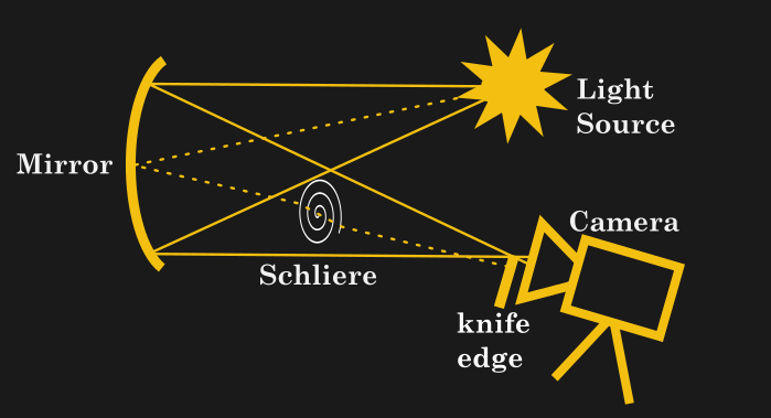
When we talk of schlieren imagery today, we generally aren’t talking about inspecting glass blanks. Most of the time, we’re talking about a family of fluid-visualization techniques. We owe that nomenclature to German physicist August Toepler, who applied these optical techniques to visualizing fluid flow in the middle of the 19th century. There is now a whole family of schlieren imaging techniques, but at the core, they all rely on one simple fact: in a fluid like air, refractive index varies by density.
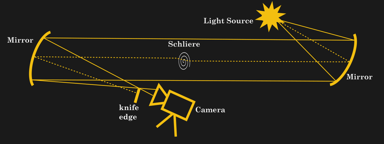
Toepler’s pioneering setup is the one we usually see in hacks nowadays. It is based on the Foucault Knife Edge Test for telescope mirrors. In Foucault’s test, a point source shines upon a concave mirror, and a razor blade is placed where the rays focus down to a point. The sensor, or Foucault’s eye, is behind the knife edge such that the returning light from the pinhole is interrupted. This has the effect of magnifying any flaws in the lens, because rays that deviate from the perfect return path will be blocked by the knife-edge and miss the eye.
Fun Schlieren Tricks
A bigger tweak uses two convex mirrors, in two-mirror or Z-path schlieren. This has two main advantages: one, the parallel rays between the mirrors mean the test area can be behind glass, useful for keeping sensitive optics outside of a high-speed wind tunnel. (This is the technique NASA used to use.) Parallel rays also ensure that the shadow of both any objects and the fluid flow are no issue; having the light source off-centre in the classic schrilien can cause artifacts from shadows. Of course you pay for these advantages: literally, in the sense that you have to buy two mirrors, and figuratively in that alignment is twice as tricky. The same colour tricks work just as well, though, and was in often use at NASA.
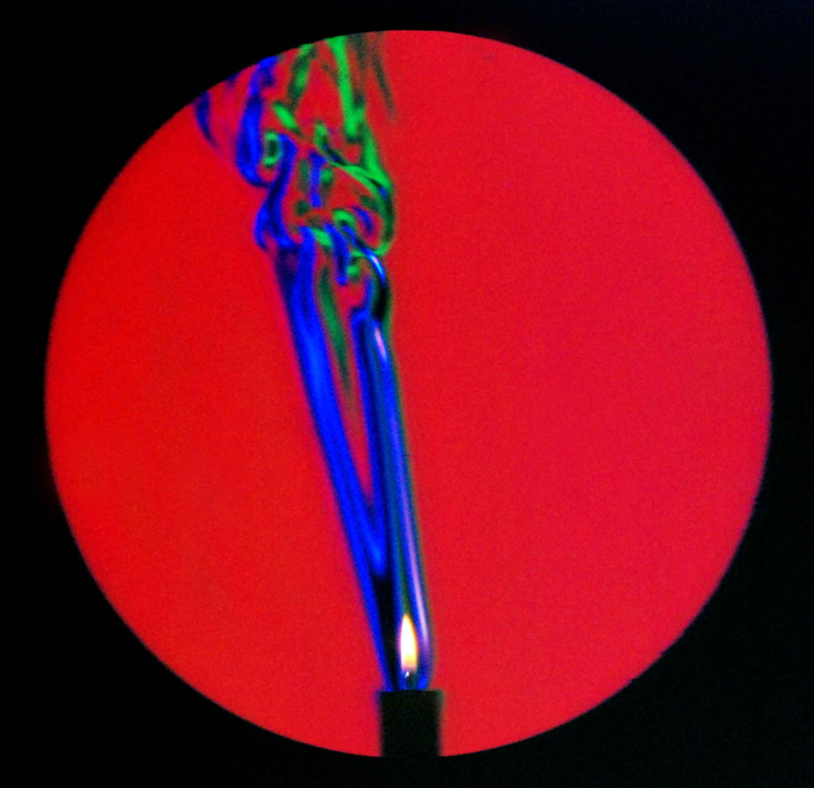
There’s absolutely no reason that you could not substitute lenses for mirrors, in either the Z-path or classical version, and people have to good effect in both cases. Indeed, Robert Hooke’s first experiment involved visualizing the flow of air above a candle using a converging lens, which was optically equivalent to Toepler’s classic single-mirror setup. Generally speaking, mirrors are preferred for the same reason you never see an 8” refracting telescope at a star party: big mirrors are way easier to make than large lenses.
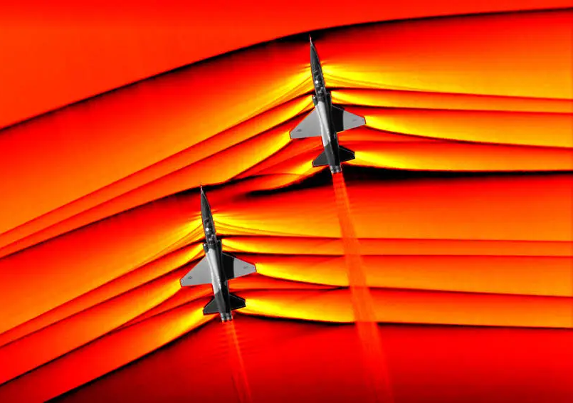
What if you want to visualize something that doesn’t fit in front of a mirror? There are actually several options. One is background-oriented schrilien, which we’ve covered here. With a known background, deviations from it can be extracted using digital signal processing techniques. We showed it working with a smart phone and a printed page, but you can use any non-uniform background. NASA uses the ground: by looking down, Airborn Background Oriented Schlieren (AirBOS) can provide flow visualization of shockwaves and vortices around an airplane in flight.
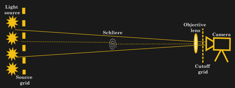
In the days before we all had supercomputers in our pockets, large-scale flow-visualization was still possible; it just needed an optical trick. A pair of matching grids is needed: one before the lamp, creating a projection of light and dark, and a second one before the lens. Rays deflected by density variations will run into the camera grid. This was used to good effect by Gary S. Styles to visualize HVAC airflows in 1997
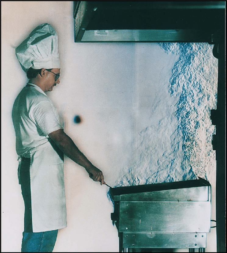
Which gets us to another application, separate from aerospace. Wind tunnel photos are very cool, but let’s be honest: most of us are not working on supersonic drones or rocket nozzles. Of course air flow does not have to be supersonic to create density variations; subsonic wind tunnels can be equipped with schlieren optics as well.
Or maybe you are more concerned with airflow around components? To ID a hotspot on a board, IR photography is much easier. On the other hand, if your hotspot is due to insufficient cooling rather than component failure? Schlieren imagery can help you visualize the flow of air around the board, letting you optimize the cooling paths.
That’s probably going to be easiest with the background-oriented version: you can just stick the background on one side of your project’s enclosure and go to work. I think that if any of you start using schlieren imaging in your projects, this might be the killer app that will inspire you to do so.
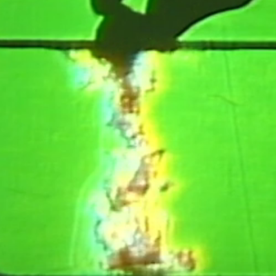
Another place we use air? In the maker space. I have yet to see someone use schlieren photography to tweak the cooling ducts on their 3D printer, but you certainly could. (It has been used to see shielding gasses in welding, for example.) For that matter, depending what you print, proper exhaust of the fumes is a major health concern. Those fumes will show up easily, given the temperature difference, and possibly even the chemical composition changing the density of the air.
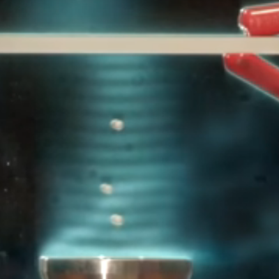
Remember that the key thing being imaged isn’t temperature difference, but density difference. Sound waves are density waves, can they be imaged in this way? Yes! The standing waves in ultrasonic levitation rigs are a popular target. Stroboscopic effects can be used for non-standing waves, though keep in mind that the sound pressure level is the inverse of frequency, so audible frequencies may not be practical if you like your eardrums.
Schlieren photography isn’t limited to air. Density variations in liquids and solids are game, too. Want to see how multiple solutions of varying density or tempeature are mixing? Schlieren imaging has you covered. Watch convection in a water tank? Or, if you happen to be making lenses, you could go right back to basics and use one of the schlieren techniques discussed here to help you make them perfect.
The real reason I’m writing about these techniques aren’t the varied applications I hope you hackers can put them to: it’s an excuse to collect all the pretty pictures of flow visualization I can cram into this article. So if you read this and thought “I have no practical reason to use this technique, but it does seem cool” – great! We’re in the same boat. Let’s make some pretty pictures. It still counts as a hack.