


![Apple Leads Global Wireless Earbuds Market in Q1 2025 [Chart]](https://www.iclarified.com/images/news/97394/97394/97394-640.jpg)

![OpenAI Acquires Jony Ive's 'io' to Build Next-Gen AI Devices [Video]](https://www.iclarified.com/images/news/97399/97399/97399-640.jpg)


![YouTube rolling out updated miniplayer on Android, iPhone [U]](https://i0.wp.com/9to5google.com/wp-content/uploads/sites/4/2024/11/YouTube-Android-app-1.jpg?resize=1200%2C628&quality=82&strip=all&ssl=1)


.webp?#)


_Alan_Wilson_Alamy.jpg?width=1280&auto=webp&quality=80&disable=upscale#)


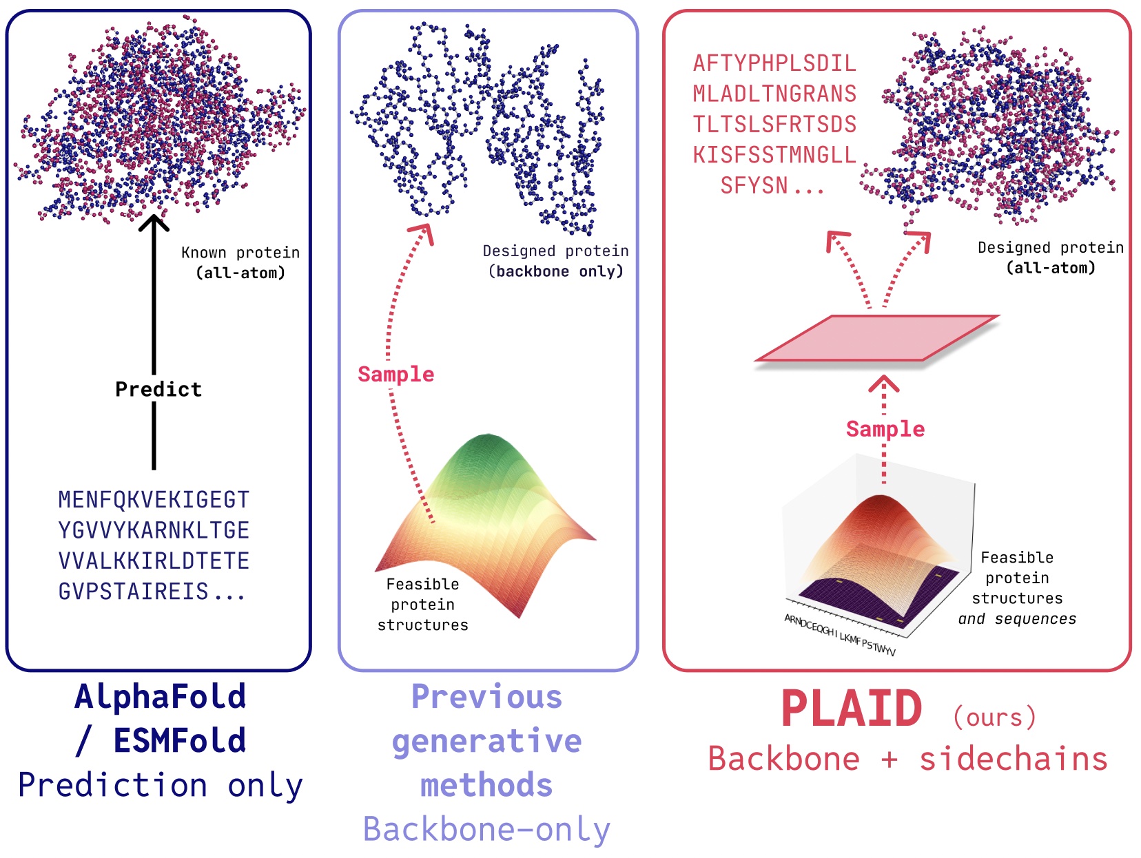
![[The AI Show Episode 148]: Microsoft’s Quiet AI Layoffs, US Copyright Office’s Bombshell AI Guidance, 2025 State of Marketing AI Report, and OpenAI Codex](https://www.marketingaiinstitute.com/hubfs/ep%20148%20cover%20%281%29.png)


![How to make Developer Friends When You Don't Live in Silicon Valley, with Iraqi Engineer Code;Life [Podcast #172]](https://cdn.hashnode.com/res/hashnode/image/upload/v1747360508340/f07040cd-3eeb-443c-b4fb-370f6a4a14da.png?#)


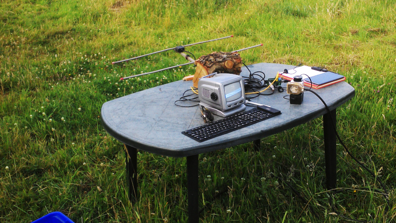
Field Testing An Antenna, Using A Field
The ARRL used to have a requirement that any antenna advertised in their publications had to have real-world measurements accompanying it, to back up any claims of extravagant performance. I’m …read more

The ARRL used to have a requirement that any antenna advertised in their publications had to have real-world measurements accompanying it, to back up any claims of extravagant performance. I’m told that nowadays they will accept computer simulations instead, but it remains true that knowing what your antenna does rather than just thinking you know what it does gives you an advantage. I was reminded of this by a recent write-up in which the performance of a mylar sheet as a ground plane was tested at full power with a field strength meter, because about a decade ago I set out to characterise an antenna using real-world measurements and readily available equipment. I was in a sense field testing it, so of course the first step of the process was to find a field. A real one, with cows.
Walking Round And Round A Field In The Name Of Science

The process I was intending to follow was simple enough. Set up the antenna in the middle of the field, have it transmit some RF, and measure the signal strength at points along a series of radial lines away from it I’d end up with a spreadsheet, from which I could make a radial plot that would I hoped, give me a diagram showing its performance. It’s a rough and ready methodology, but given a field and a sunny afternoon, not one that should be too difficult.
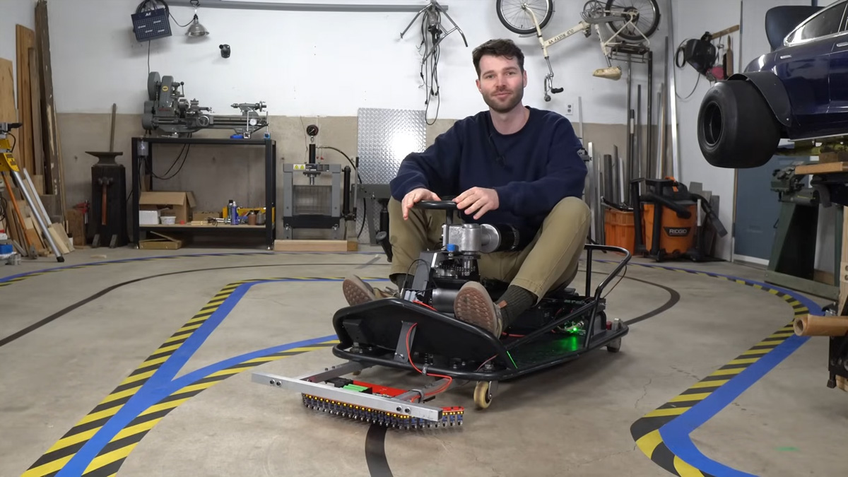
I was more interested in the process than the antenna, so I picked up my trusty HB9CV two-element 144MHz antenna that I’ve stood and pointed at the ISS many times to catch SSTV transmissions. It’s made from two phased half-wave radiators, but it can be seen as something similar to a two-element Yagi array. I ran a long mains lead oput to a plastic garden table with the HB9CV attached, and set up a Raspberry Pi whose clock would produce the RF.
My receiver would be an Android tablet with an RTL-SDR receiver. That’s pretty sensitive for this purpose, so my transmitter would have to be extremely low powered. Ideally I would want no significant RF to make it beyond the boundary of the field, so I gave the Pi a resistive attenuator network designed to give an output of around 0.03 mW, or 30 μW. A quick bit of code to send my callsign as CW periodically to satisfy my licence conditions, and I was off with the tablet and a pen and paper. Walking round the field in a polar grid wasn’t as easy as it might seem, but I had a very long tape measure to help me.
A Lot Of Work To Tell Me What I Already Knew

I ended up with a page of figures, and then a spreadsheet which I’m amused to still find in the depths of my project folder. It contains a table of angles of incidence to the antenna versus metres from the antenna, and the data points are the figure in (uncalibrated) mV that the SDR gave me for the carrier at that point. The resulting polar plot shows the performace of the antenna at each angle, and unsurprisingly I proved to myself that a HB9CV is indeed a directional antenna.
My experiment was in itself not of much use other than to prove to myself I could characterise an antenna with extremely basic equipment. But then again it’s possible that in times past this might have been a much more difficult task, so knowing I can do it at all is an interesting conclusion.