


![Apple Reorganizes Executive Team to Rescue Siri [Report]](https://www.iclarified.com/images/news/96777/96777/96777-640.jpg)


![The latest vinyl Android figure is a faux wood ‘Pine Pal’ where no two are alike [Gallery]](https://i0.wp.com/9to5google.com/wp-content/uploads/sites/4/2025/03/android-figure-pine-pal-1.jpg?resize=1200%2C628&quality=82&strip=all&ssl=1)


![[The AI Show Episode 139]: The Government Knows AGI Is Coming, Superintelligence Strategy, OpenAI’s $20,000 Per Month Agents & Top 100 Gen AI Apps](https://www.marketingaiinstitute.com/hubfs/ep%20139%20cover-2.png)


![[The AI Show Episode 138]: Introducing GPT-4.5, Claude 3.7 Sonnet, Alexa+, Deep Research Now in ChatGPT Plus & How AI Is Disrupting Writing](https://www.marketingaiinstitute.com/hubfs/ep%20138%20cover.png)


-Assassin's-Creed-Shadows-Review-00-12-31.png?width=1920&height=1920&fit=bounds&quality=80&format=jpg&auto=webp#)


![Release: Rendering Ranger: R² [Rewind]](https://images-3.gog-statics.com/48a9164e1467b7da3bb4ce148b93c2f92cac99bdaa9f96b00268427e797fc455.jpg)


Using single chip microcomputer to realize ultrasonic obstacle avoidance car
Creating an ultrasonic obstacle avoidance car using a single-chip microcontroller is a popular embedded systems project. The car uses an ultrasonic sensor to detect obstacles and adjusts its movement accordingly. Below is a step-by-step guide to designing and implementing this project: 1. System Overview The system consists of: Microcontroller: Acts as the brain of the car (e.g., STM32, ESP32, Arduino, or PIC). Ultrasonic Sensor: Measures the distance to obstacles (e.g., HC-SR04). Motor Driver: Controls the motors for movement (e.g., L298N or TB6612FNG). DC Motors: Drive the wheels of the car. Power Supply: Provides power to the microcontroller, motors, and sensors. 2. Hardware Components Microcontroller: STM32, ESP32, or Arduino. Ultrasonic Sensor: HC-SR04. Motor Driver: L298N or TB6612FNG. DC Motors: Two or four motors for movement. Chassis: A car chassis with wheels. Power Supply: Batteries (e.g., 9V or 12V) and voltage regulators (e.g., 5V for the microcontroller). Jumper Wires and Breadboard: For connections. 3. Circuit Design Ultrasonic Sensor Connection: VCC: Connect to 5V. GND: Connect to GND. Trig: Connect to a GPIO pin (e.g., PA0). Echo: Connect to another GPIO pin (e.g., PA1). Motor Driver Connection: IN1, IN2, IN3, IN4: Connect to GPIO pins (e.g., PB0, PB1, PB2, PB3). ENA, ENB: Connect to PWM-capable GPIO pins (e.g., PA8, PA9). VCC: Connect to the motor power supply (e.g., 9V). GND: Connect to GND. OUT1, OUT2, OUT3, OUT4: Connect to the DC motors. Power Supply: Use a voltage regulator (e.g., LM7805) to provide 5V to the microcontroller and sensors. Connect the motor power supply directly to the motor driver. 4. Software Design Step 1: Initialize Peripherals Configure GPIO pins for the ultrasonic sensor and motor driver. Set up timers for PWM (to control motor speed). Step 2: Measure Distance Use the ultrasonic sensor to measure the distance to obstacles. Send a 10µs pulse to the Trig pin. Measure the pulse width on the Echo pin to calculate the distance. Step 3: Control Motors Use the motor driver to control the direction and speed of the motors. Implement functions for forward, backward, left, right, and stop movements. Step 4: Implement Obstacle Avoidance Logic If an obstacle is detected within a certain distance (e.g., 20 cm), stop or reverse the car. Turn left or right to avoid the obstacle. 5. Example Code (STM32CubeIDE) Ultrasonic Sensor Code c #include "stm32f4xx_hal.h" #define TRIG_PIN GPIO_PIN_0 #define TRIG_PORT GPIOA #define ECHO_PIN GPIO_PIN_1 #define ECHO_PORT GPIOA uint32_t get_distance(void) { // Send 10µs pulse to Trig pin HAL_GPIO_WritePin(TRIG_PORT, TRIG_PIN, GPIO_PIN_SET); HAL_Delay(0.01); // 10µs delay HAL_GPIO_WritePin(TRIG_PORT, TRIG_PIN, GPIO_PIN_RESET); // Measure pulse width on Echo pin uint32_t start_time = 0, end_time = 0; while (HAL_GPIO_ReadPin(ECHO_PORT, ECHO_PIN) == GPIO_PIN_RESET); start_time = HAL_GetTick(); while (HAL_GPIO_ReadPin(ECHO_PORT, ECHO_PIN) == GPIO_PIN_SET); end_time = HAL_GetTick(); // Calculate distance (in cm) uint32_t pulse_width = end_time - start_time; uint32_t distance = pulse_width * 0.034 / 2; // Speed of sound = 340 m/s return distance; } Motor Control Code c void move_forward(void) { HAL_GPIO_WritePin(GPIOB, GPIO_PIN_0, GPIO_PIN_SET); // IN1 HAL_GPIO_WritePin(GPIOB, GPIO_PIN_1, GPIO_PIN_RESET); // IN2 HAL_GPIO_WritePin(GPIOB, GPIO_PIN_2, GPIO_PIN_SET); // IN3 HAL_GPIO_WritePin(GPIOB, GPIO_PIN_3, GPIO_PIN_RESET); // IN4 } void move_backward(void) { HAL_GPIO_WritePin(GPIOB, GPIO_PIN_0, GPIO_PIN_RESET); // IN1 HAL_GPIO_WritePin(GPIOB, GPIO_PIN_1, GPIO_PIN_SET); // IN2 HAL_GPIO_WritePin(GPIOB, GPIO_PIN_2, GPIO_PIN_RESET); // IN3 HAL_GPIO_WritePin(GPIOB, GPIO_PIN_3, GPIO_PIN_SET); // IN4 } void turn_left(void) { HAL_GPIO_WritePin(GPIOB, GPIO_PIN_0, GPIO_PIN_RESET); // IN1 HAL_GPIO_WritePin(GPIOB, GPIO_PIN_1, GPIO_PIN_SET); // IN2 HAL_GPIO_WritePin(GPIOB, GPIO_PIN_2, GPIO_PIN_SET); // IN3 HAL_GPIO_WritePin(GPIOB, GPIO_PIN_3, GPIO_PIN_RESET); // IN4 } void turn_right(void) { HAL_GPIO_WritePin(GPIOB, GPIO_PIN_0, GPIO_PIN_SET); // IN1 HAL_GPIO_WritePin(GPIOB, GPIO_PIN_1, GPIO_PIN_RESET); // IN2 HAL_GPIO_WritePin(GPIOB, GPIO_PIN_2, GPIO_PIN_RESET); // IN3 HAL_GPIO_WritePin(GPIOB, GPIO_PIN_3, GPIO_PIN_SET); // IN4 } void stop(void) { HAL_GPIO_WritePin(GPIOB, GPIO_PIN_0, GPIO_PIN_RESET); // IN1 HAL_GPIO_WritePin(GPIOB, GPIO_PIN_1, GPIO_PIN_RESET); // IN2 HAL_GPIO_WritePin(GPIOB, GPIO_PIN_2, GPIO_PIN_RESET); // IN3 HAL_GPIO_WritePin(GPIOB, GPIO_PIN_3, GPIO_PIN_RESET); // IN4 } Main Code c int main(void) { HAL_Init(); SystemClock_Config(); GPIO_Init(); while (1) { uint32_t distance = get_distance(); if (distance < 20) { // Obstacle detected stop(); HAL_Delay(500); move_backw
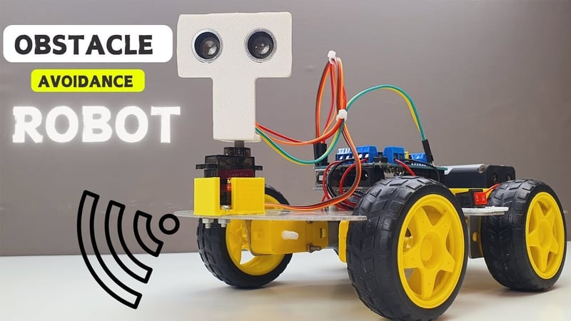
Creating an ultrasonic obstacle avoidance car using a single-chip microcontroller is a popular embedded systems project. The car uses an ultrasonic sensor to detect obstacles and adjusts its movement accordingly. Below is a step-by-step guide to designing and implementing this project:
1. System Overview
The system consists of:
- Microcontroller: Acts as the brain of the car (e.g., STM32, ESP32, Arduino, or PIC).
- Ultrasonic Sensor: Measures the distance to obstacles (e.g., HC-SR04).
- Motor Driver: Controls the motors for movement (e.g., L298N or TB6612FNG).
- DC Motors: Drive the wheels of the car.
- Power Supply: Provides power to the microcontroller, motors, and sensors.
2. Hardware Components
Microcontroller: STM32, ESP32, or Arduino.
Ultrasonic Sensor: HC-SR04.
Motor Driver: L298N or TB6612FNG.
DC Motors: Two or four motors for movement.
Chassis: A car chassis with wheels.
Power Supply: Batteries (e.g., 9V or 12V) and voltage regulators (e.g., 5V for the microcontroller).
Jumper Wires and Breadboard: For connections.
3. Circuit Design
- Ultrasonic Sensor Connection:
- VCC: Connect to 5V.
- GND: Connect to GND.
- Trig: Connect to a GPIO pin (e.g., PA0).
- Echo: Connect to another GPIO pin (e.g., PA1).
- Motor Driver Connection:
- IN1, IN2, IN3, IN4: Connect to GPIO pins (e.g., PB0, PB1, PB2, PB3).
- ENA, ENB: Connect to PWM-capable GPIO pins (e.g., PA8, PA9).
- VCC: Connect to the motor power supply (e.g., 9V).
- GND: Connect to GND.
- OUT1, OUT2, OUT3, OUT4: Connect to the DC motors.
- Power Supply:
- Use a voltage regulator (e.g., LM7805) to provide 5V to the microcontroller and sensors.
- Connect the motor power supply directly to the motor driver.
4. Software Design
Step 1: Initialize Peripherals
- Configure GPIO pins for the ultrasonic sensor and motor driver.
- Set up timers for PWM (to control motor speed).
Step 2: Measure Distance
- Use the ultrasonic sensor to measure the distance to obstacles.
- Send a 10µs pulse to the Trig pin.
- Measure the pulse width on the Echo pin to calculate the distance.
Step 3: Control Motors
- Use the motor driver to control the direction and speed of the motors.
- Implement functions for forward, backward, left, right, and stop movements.
Step 4: Implement Obstacle Avoidance Logic
- If an obstacle is detected within a certain distance (e.g., 20 cm), stop or reverse the car.
- Turn left or right to avoid the obstacle.
5. Example Code (STM32CubeIDE)
Ultrasonic Sensor Code
c

#include "stm32f4xx_hal.h"

#define TRIG_PIN GPIO_PIN_0
#define TRIG_PORT GPIOA
#define ECHO_PIN GPIO_PIN_1
#define ECHO_PORT GPIOA

uint32_t get_distance(void) {
    // Send 10µs pulse to Trig pin
    HAL_GPIO_WritePin(TRIG_PORT, TRIG_PIN, GPIO_PIN_SET);
    HAL_Delay(0.01); // 10µs delay
    HAL_GPIO_WritePin(TRIG_PORT, TRIG_PIN, GPIO_PIN_RESET);

    // Measure pulse width on Echo pin
    uint32_t start_time = 0, end_time = 0;
    while (HAL_GPIO_ReadPin(ECHO_PORT, ECHO_PIN) == GPIO_PIN_RESET);
    start_time = HAL_GetTick();
    while (HAL_GPIO_ReadPin(ECHO_PORT, ECHO_PIN) == GPIO_PIN_SET);
    end_time = HAL_GetTick();

    // Calculate distance (in cm)
    uint32_t pulse_width = end_time - start_time;
    uint32_t distance = pulse_width * 0.034 / 2; // Speed of sound = 340 m/s
    return distance;
}
Motor Control Code
c

void move_forward(void) {
    HAL_GPIO_WritePin(GPIOB, GPIO_PIN_0, GPIO_PIN_SET); // IN1
    HAL_GPIO_WritePin(GPIOB, GPIO_PIN_1, GPIO_PIN_RESET); // IN2
    HAL_GPIO_WritePin(GPIOB, GPIO_PIN_2, GPIO_PIN_SET); // IN3
    HAL_GPIO_WritePin(GPIOB, GPIO_PIN_3, GPIO_PIN_RESET); // IN4
}

void move_backward(void) {
    HAL_GPIO_WritePin(GPIOB, GPIO_PIN_0, GPIO_PIN_RESET); // IN1
    HAL_GPIO_WritePin(GPIOB, GPIO_PIN_1, GPIO_PIN_SET); // IN2
    HAL_GPIO_WritePin(GPIOB, GPIO_PIN_2, GPIO_PIN_RESET); // IN3
    HAL_GPIO_WritePin(GPIOB, GPIO_PIN_3, GPIO_PIN_SET); // IN4
}

void turn_left(void) {
    HAL_GPIO_WritePin(GPIOB, GPIO_PIN_0, GPIO_PIN_RESET); // IN1
    HAL_GPIO_WritePin(GPIOB, GPIO_PIN_1, GPIO_PIN_SET); // IN2
    HAL_GPIO_WritePin(GPIOB, GPIO_PIN_2, GPIO_PIN_SET); // IN3
    HAL_GPIO_WritePin(GPIOB, GPIO_PIN_3, GPIO_PIN_RESET); // IN4
}

void turn_right(void) {
    HAL_GPIO_WritePin(GPIOB, GPIO_PIN_0, GPIO_PIN_SET); // IN1
    HAL_GPIO_WritePin(GPIOB, GPIO_PIN_1, GPIO_PIN_RESET); // IN2
    HAL_GPIO_WritePin(GPIOB, GPIO_PIN_2, GPIO_PIN_RESET); // IN3
    HAL_GPIO_WritePin(GPIOB, GPIO_PIN_3, GPIO_PIN_SET); // IN4
}

void stop(void) {
    HAL_GPIO_WritePin(GPIOB, GPIO_PIN_0, GPIO_PIN_RESET); // IN1
    HAL_GPIO_WritePin(GPIOB, GPIO_PIN_1, GPIO_PIN_RESET); // IN2
    HAL_GPIO_WritePin(GPIOB, GPIO_PIN_2, GPIO_PIN_RESET); // IN3
    HAL_GPIO_WritePin(GPIOB, GPIO_PIN_3, GPIO_PIN_RESET); // IN4
}
Main Code
c

int main(void) {
    HAL_Init();
    SystemClock_Config();
    GPIO_Init();

    while (1) {
        uint32_t distance = get_distance();

        if (distance < 20) { // Obstacle detected
            stop();
            HAL_Delay(500);
            move_backward();
            HAL_Delay(500);
            turn_left();
            HAL_Delay(500);
        } else { // No obstacle
            move_forward();
        }
    }
}
6. Testing and Debugging
- Test the Ultrasonic Sensor:
Verify that the sensor accurately measures distance.
- Test Motor Control:
Ensure the motors move in the correct direction and speed.
- Test Obstacle Avoidance:
Place obstacles in front of the car and verify that it avoids them.
7. Enhancements
- Add Speed Control:
Use PWM to control motor speed.
- Add Multiple Sensors:
Use multiple ultrasonic sensors for better obstacle detection.
- Add Bluetooth/Wi-Fi Control:
Use an ESP32 to add remote control via a smartphone app.
- Add Display:
Use an LCD or OLED to display distance and status.
By following these steps, you can build an ultrasonic obstacle avoidance car using a single-chip microcontroller.